
BVT-DLH Floating-Liner Steam Attemperator
The BVT-DLH controls steam superheat in boilers and Heat Recovery Steam Generators using multiple spring-loaded spray-water nozzles. Its unwelded floating liner protects the steam pipe and profiles the flow while allowing thermal expansion. A separate water control valve regulates the spray-water flow.
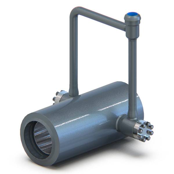
How the BVT-DLH works
Water enters the superheated steam perpendicular to the steam flow through a series of spring-loaded atomizing nozzles. The spray is distributed across the steam pipe to support cooling and evaporation. The external water control valve is selected for the required water-flow and pressure conditions.
The floating liner shields the steam pipe from thermal stresses and increases relative steam velocity near the nozzles. Unlike a welded liner, it is installed without welding and can move as the material expands. B-006 describes this construction as more resistant to cycling.
The liner and nozzle arrangement are parts of the complete temperature-control design. The downstream sensor must measure steam after adequate mixing and evaporation, and the water valve must follow the actual steam-cooling demand. Published component ratings do not replace a review of transient operation and available pipe distances.
Applications and selection
The DLH is an attemperator for boiler and HRSG superheat control. The brochure shows inter-stage and final-stage positions in a boiler arrangement. Select the location and required temperature response around the thermal limits of the connected boiler, superheater and turbine system.
The floating liner is a distinguishing feature where thermal cycling is important. B-006 publishes cycling capability up to 6300 cycles over 25 years, but the applicable cycle definition, operating envelope and project duty must be confirmed for the selected design rather than treated as a general service-life guarantee.
Key features
- Unwelded floating flow-profiling liner.
- Multiple spring-loaded spray-water nozzles.
- Nozzles made from Inconel 718.
- Designed for large spray-water flows and even distribution.
- Construction intended to accommodate thermal expansion and cycling.
Specifications
| Nozzle material | Inconel 718 |
|---|---|
| Rangeability | Determined by the external spray-water control valve |
| Steam design pressure | 200 bar(g) |
| Water design pressure | 320 bar(g) |
| Steam design temperature | 630 °C |
| Water design temperature | 250 °C |
| Published cycling capability | Up to 6300 cycles / 25 years; confirm project duty |
| Recommended installation | Horizontal, or vertical with steam flowing upwards |
Specifications follow B-006. Confirm the combined pressure-temperature rating and cyclic duty for the delivered equipment. The floating liner must not be treated as a welded-liner assembly during service.
Installation and service guidance
Use product manual M-007, BVT general instructions M-001 and the drawings supplied for the installation. These notes are an overview, not a substitute for the equipment-specific instructions. Installation, commissioning and service must be carried out by trained personnel within the specified service conditions.
Product-specific installation requirements
B-006 recommends horizontal installation or vertical installation with steam flowing upwards. Follow the supplied liner supports, flow direction and nozzle arrangement, and leave the required access for inspection and service.
M-007 includes the DLH in its combined product scope, but not every procedure applies to every liner variant. Use the equipment-specific floating-liner instructions and drawings; do not apply welded-liner repair procedures to the unwelded floating liner. Contact BVT if the applicable procedure is unclear.
Before commissioning
Check the delivered equipment and connections against the order documentation. Confirm the intended operating conditions, installation orientation and the functions of the associated control equipment before starting the system. Keep access available for inspection and servicing. If the proposed installation differs from the supplied drawings or operating conditions, contact BVT before proceeding.
Safe access and maintenance planning
Before service, isolate the equipment from the process and disconnect the applicable electrical, pneumatic or hydraulic supplies. Confirm that pressure-retaining equipment is depressurized and sufficiently cooled. Account for stored energy, including actuator springs and trapped pressure; disconnecting a supply alone does not remove every hazard. Wear the required protective equipment and follow local safety procedures.
Use the product manual for component replacement and service procedures, and identify spare parts from the supplied documentation. Do not alter the equipment or instrument settings without confirming the consequences with BVT. Detailed disassembly instructions and tightening torques belong in the applicable service documentation.
Frequently asked questions
- What is special about the DLH liner?
- It is an unwelded floating liner that can move with thermal expansion. It also protects the steam pipe from thermal stress and profiles the steam flow near the nozzles.
- Does the DLH use one nozzle or several?
- B-006 describes a series of spring-loaded atomizing nozzles. The DLBS is a different product with a single-nozzle arrangement; its layout should not be assumed for the DLH.
- Where is the DLH used?
- It is used for controlling steam superheat in boilers and HRSGs. The brochure illustrates both inter-stage and final-stage attemperator positions.
- What pressure and temperature limits are published?
- B-006 lists steam design pressure of 200 bar(g), water design pressure of 320 bar(g), steam design temperature of 630 °C and water design temperature of 250 °C. Confirm the selected equipment's combined operating envelope.
- Which installation directions are recommended?
- Horizontal installation or vertical installation with the steam flowing upwards is recommended. Follow the project drawings and review any different arrangement with BVT.
- What does the cycling figure mean?
- The brochure lists up to 6300 cycles over 25 years. Confirm the relevant cycle definition and thermal duty with BVT; the figure is not an unconditional service-life guarantee for arbitrary operating conditions.
Product documentation
Download B-006 BVT-DLH brochure (PDF)
For installation and service, use product manual M-007 together with BVT general instructions M-001 and the documentation supplied for your equipment. Contact BVT for the applicable manual revision, installation drawings and spare parts identification.
Related BVT products
Contact BVT Sweden with the operating conditions and required functionality for application-specific selection.