
BVT-TB Steam Conditioning Valve
Angle-style turbine bypass and process steam letdown valve — up to 500 mm seat diameter, ANSI 4500, 620 °C

How the BVT-TB works
The BVT-TB is designed to reduce the temperature and pressure of steam to match downstream requirements. Pressure is controlled using a proven trim technology in which a series of perforations in the valve cage are progressively revealed as the plug moves. Steam then passes to the outlet through a series of pressure reduction stages. These stages are selected specifically for the operating conditions on a case-by-case basis in order to reduce noise, and the pressure reduction pipes also create a flow profile that improves atomization of the spray water.
The valve plug design is optimized for low actuating forces. This balanced design allows smaller actuators to be used, and makes pneumatic actuation viable on valve sizes that would otherwise demand hydraulic actuation.
Control of temperature takes place in the outlet, where a number of spring-loaded spray water atomizing nozzles are installed perpendicular to the steam flow. The selection, placement and design of these nozzles are chosen to match the desuperheating requirements of the system, and to reduce the risk of free water being injected into the downstream piping. The nozzles are spring loaded to avoid thermal cracks in the outlet pipe and can be replaced quickly and easily.
Applications
Turbine bypass system
During startup, shutdown and turbine trip, the steam normally passed through the turbine is bypassed by steam conditioning valves into the condenser, to a downstream process or to the atmosphere. This allows the power delivery from the turbines to be closed, while still recycling the steam. The turbine bypass system consists of both pressure reduction and steam desuperheating. Valves used in this application must provide low noise, high flow and pressure drop capabilities, while also being suitable for large temperature differences.
- HRSG
- High-pressure steam isolation valve
- Condensate pump
- High-pressure steam conditioning valve (BVT-TB)
- Spray water control / isolation valves
- Low-pressure steam isolation valve
- Condenser
- Low-pressure steam conditioning valve (BVT-TB) / dump tube
- Spray water control / isolation valves
Typical markets
- Combined cycle power plants
- Combined heat and power (CHP) plants
- Concentrated solar power (CSP) plants
- Process steam plants requiring conditioned steam export
Specifications
| Valve style | Angle-style, forged body |
|---|---|
| Valve sizes | Up to 500 mm seat diameter |
| Pressure class | Up to ANSI 4500 (higher rating on request) |
| Design temperature | 620 °C as standard (650 °C on request) |
| Leakage class | ANSI Class III, IV, V; MSS SP-61 |
| Rangeability | Up to 25:1 for the complete valve |
| Regulatory requirements | ASME, EN, PED, IBR, CRN. Manufactured under ISO 9001 and ISO 14001. |
| Materials | Forged material adapted to connecting pipe material |
| Bonnet | Pressure seal bonnet |
| Actuation | Pneumatic, hydraulic or electrical |
| Connections | Fully customizable inlet and outlet connections |
Options
- Quick change type seat — reduces maintenance downtime
- Erosion resistant trim with long cage — reduces wear on trim internals caused by wet steam or particles by moving the critical pressure drop
- Expanded outlet — improves secondary atomization through increased steam velocity over the nozzles, improves tertiary atomization and increases rangeability
- Live load gland seal packings
Key features
- Fully customizable inlet and outlet connections.
- Complies with ASME, EN and PED.
- Forged valve body with uniform thickness, and trim design optimized to withstand thermal cycling.
- High shut-off class (to ANSI Class V).
- Great rangeability, up to 25:1 for the complete valve.
- Pressure reduction stages and spray nozzle arrangements optimized for the actual operating conditions and for reduced noise. The pressure reduction pipes also create a flow profile that improves atomization.
- Balanced plug design requires smaller actuating forces, allowing smaller and pneumatic actuators.
- Pressure seal bonnet for simpler and quicker maintenance — no special tools necessary.
- Compatible with pneumatic, hydraulic and electrical actuation.
- Easily exchangeable seat available as an option for further reduced maintenance downtime.
- Optimized packing design.
- Long cage design reduces wear on trim internals caused by wet steam or particles.
- Spring-loaded nozzles designed to avoid thermal cracks in the outlet pipe; quickly and easily replaced.
Actuation options
Pneumatic actuation
BVT valves can be equipped with the BVT-PD linear pneumatic piston actuator, mounted on top of the valve with a coupling to the valve stem. Each actuator is sized to the force requirements of the valve and to the customer’s stroke time and functional requirements. It is also available as an upgrade for existing valves.
A positioner modulates the actuator from a 4–20 mA set-point signal, with volume boosters added where higher stroke speed is needed. By default the actuator has a quick open or quick close function: if the supply pressure drops below a set level, the modulating operation is overridden and the valve is driven to its safe position, using air stored in an air tank (double acting) or a spring (single acting).
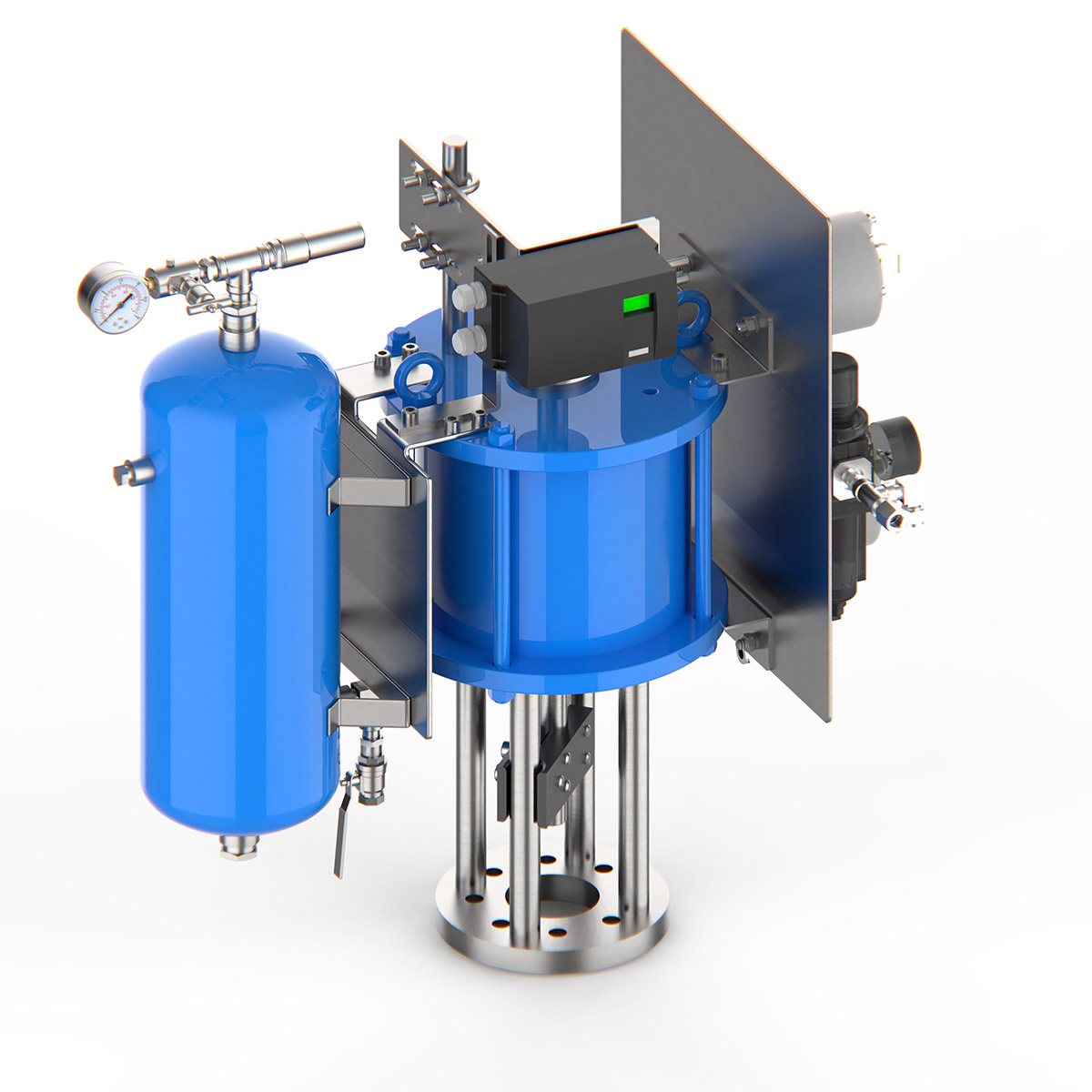
| Types | Double acting or single acting (spring open or spring close); modulating or on/off |
|---|---|
| Air supply | 4 – 10 bar |
| Operating temperature | −20 to 80 °C (standard) |
| Cylinder sizes | Up to 900 mm |
| Protection | Components IP65/IP67; cylinder corrosion protection ISO 12944 C4 or C5M; ANSI 316 tubes and fittings |
| Standard accessories | Air filter regulator, positioner, pressure sensing valve for quick function |
| Optional accessories | Volume boosters, solenoid valves, limit switches, position transmitter, top or side mounted hand wheel |
| Compliance | ASME, PED, ISO 9001/14001; ATEX and SIL as option |
Electro-hydraulic actuation
Commissioning tools and hydraulic pipes, fittings and hoses are also available.
Installation, commissioning and maintenance
The following summarises requirements from BVT product manual M-004 and general instructions M-001. These are general guidelines — any individual installation may require special considerations, and if the stated pipe distances cannot be achieved, contact BVT Sweden AB for an installation-specific calculation.
Important: all BVT steam valves are designed for dry steam. Wet steam, condensate and magnetite damage valves, and such damage is not covered by warranty. Drains and vent valves must take care of pipe prewarming.
Minimum pipe distances
Non-uniform upstream flow patterns create rotational forces that strain valve parts, and injected water droplets need time and distance to fully evaporate. Where multiple criteria apply, the highest value must be used.
| Distance | Condition | Must exceed |
|---|---|---|
| Straight pipe upstream of inlet (L1) | Single upstream bend, Ø < 200 mm | 1 metre |
| Single upstream bend, Ø 200–400 mm | 5 × Ø | |
| Single upstream bend, Ø > 400 mm | 3 × Ø | |
| Multiple upstream bends, Ø < 200 mm | 3 metres | |
| Multiple upstream bends, Ø 200–400 mm | 15 × Ø | |
| Multiple upstream bends, Ø > 400 mm | 9 × Ø | |
| Straight pipe downstream of water injection (L2) | BVT-TB, mechanical atomization — bypass to process, to cold reheat or to district heating | 0.1 s × V, maximum 8 × Ø |
| Water injection to downstream temperature sensor (L3) | Water-to-steam ratio r < 15% | 0.2 s × V, maximum 12 metres |
| Water-to-steam ratio 15% ≤ r < 18% | (0.2 + (r − 15%) / 0.3) s × V, maximum 12 metres | |
| Water-to-steam ratio r ≥ 18% | 0.3 s × V, maximum 12 metres |
Avoid multiple bends upstream of the valve, as these cause rotational steam flow.
Drainage
Water entering a steam conditioning valve can damage internal parts and disturb downstream temperature measurement, so drains are required both upstream and downstream of the valve. Maximum condensate normally occurs during cold startup and must be considered at the design stage when sizing the drainage system. As an estimate, a water mass of typically 7–14% of the upstream piping weight needs to be removed through the condensate system during startup.
An undersized upstream drainage system that cannot handle condensate from pipe warming during a cold start is the most common cause of valve damage. The drain valve should remain open during startup and any other condition producing condensate, and must stay open until the steam is above saturation + 20 °C. A temperature sensor should always confirm that upstream steam is dry before the valve is opened.
Temperature sensor placement
The downstream temperature sensor must be positioned where it measures the temperature actually being controlled. If it is installed too close to the spray water injection point it may be struck by unevaporated droplets, producing a false low reading and unstable temperature control. No branches, isolation valves or other obstructions may be placed in the steam line between the spray water injection point and the temperature sensor. A higher degree of superheat or a higher water temperature shortens the required distance; lower values lengthen it. BVT can supply a protective shield that encases the sensor, installed with its hole facing downstream.
BVT also recommends installing a temperature sensor and a pressure sensor upstream of the steam conditioning valve, both to confirm dry steam before the valve opens and to support feed-forward outlet temperature control.
Insulation
Any valve intended for hot service must be insulated. Thermal insulation should be applied to all exterior surfaces of the valve body and bonnet, and should help keep the body adequately warm while the valve is closed. Proper insulation minimises heat loss, maintains thermal stability, reduces the risk of condensation and water hammer, and improves personnel safety.
- Insulate the valve body, inlet and outlet piping, and adjacent flanges.
- Do not insulate actuators, positioners or other temperature-sensitive electrical equipment — the actuator and its accessories must be protected from excessive heat.
- Do not cover the yokes or add material that makes removing valve internals difficult.
- Ensure the insulation does not interfere with plug or stem movement.
- Keep nozzle cover plates accessible and uncovered.
- The insulation must not trap condensate around the valve body.
Insulation also provides noise attenuation. A −10 dBA arrangement uses 1 mm cladding steel plate over 300 mm mineral wool at 200 kg/m³ density. A −15 dBA arrangement adds a heavy self-adhesive noise damping layer (approx. 7 kg/m²) and a 50 mm mineral wool layer between two cladding plates.
Body material temperature limits
| Carbon steel (internals Tenifer surface hardened) | 480 °C |
|---|---|
| Low alloy steel | 580 °C |
| 13CrMo4-5 / ASTM Gr.12 | 580 °C |
| 11CrMo9-10 / ASTM Gr.22 | 580 °C |
| X10CrMoVNb9-1 / ASTM Gr.91 | 580 °C |
| Low alloy steel (internals Cobalt hard faced) | 650 °C |
Before welding into the pipeline
- Verify that the installation direction is correct, and that any arrow on the valve body points in the same direction as the flow in the pipe system.
- Align the pipe ends properly so the valve is not subjected to unnecessary strain.
- Remove the valve trim and spray nozzles before welding the valve into the pipeline.
- Remove any commissioning tools (hydrotest, blowout, etc.) before welding.
- Welding and any necessary heat treatment are the contractor’s responsibility and must be performed in compliance with applicable standards by qualified personnel.
Commissioning and steam blowing
Debris generated during installation or major repair can damage valve trim and sealing surfaces, clog spray nozzles and cause improper valve operation. Steam blowing removes loose particles from the pipework, but the procedure itself can severely damage trim parts, so protective equipment such as a blow out tool, blow through tool, dummy nozzles or sacrificial trims must be installed first. BVT must be informed of the planned steam blowing method in advance and can supply the required tools.
| Steam temperature | 50 – 100 °C above saturation point |
|---|---|
| Steam velocity | More than 50% of maximum steam velocity, and at least 70 m/s |
| Max. temperature for BVT steam blowing tools | 425 °C as standard |
If the steam velocity is too low, particles may not be carried along and can fall back into the pipework where they are difficult to detect.
Upstream stop valve
An undersized steam stop valve creates a high pressure drop as it constricts the flow, which in turn gives the steam control valve a non-linear characteristic. Undersized stop valves with a reduced bore upstream of a steam control valve are known to cause noise and vibration due to high vena contracta velocities and non-uniform velocity distribution. An angle-style stop valve can be welded directly to the inlet connection of the BVT-TB as a single unit, but BVT must be informed in advance if such an arrangement is planned.
Maintenance notes
- Confirm that the pressure vessel is depressurized and sufficiently cooled down before starting any work, and wear protective gloves, clothing and eye-wear.
- Before maintenance on a valve in an operational facility, a double block-and-bleed configuration must be installed upstream. Each component in the block-and-bleed system must be individually proven for the highest expected pressure.
- Ensure the packing gland is firmly tightened before pressurizing the valve. Never remove the gland nut or flange while the valve is pressurized.
- Ensure drain and vent valves are open and discharging.
- The pressure seal must be replaced after every disassembly.
- Stem packing rings must be replaced after every disassembly.
- The valve and yoke must never be lifted using the actuator or eye bolts installed on the actuator.
- If live load is used, note the compressed height of the belle-ville washer sets before removing the gland yoke nuts.
- No alteration should be made to any valve without the involvement of BVT service engineers.
Frequently asked questions
- What is the BVT-TB steam conditioning valve?
- An angle-style steam conditioning valve from BVT Sweden that combines multi-stage pressure reduction with integrated spray-water desuperheating in a single forged body. It is used for turbine bypass and process steam letdown.
- What is a turbine bypass valve used for?
- Turbine bypass valves are installed in parallel with the turbine’s pressure stages and provide a secondary conduit for superheated steam. They control downstream pressure and temperature during normal turbine operation or during a turbine trip, conditioning the steam so it can be passed to a condenser or to process.
- What sizes and pressure ratings are available?
- Up to 500 mm seat diameter and up to ANSI 4500, with higher ratings on request.
- What is the maximum design temperature?
- 620 °C as standard and 650 °C on request.
- What is the rangeability of the BVT-TB?
- Up to 25:1 for the complete valve. An expanded outlet is available as an option, which increases rangeability and improves atomization through higher steam velocity over the nozzles.
- What leakage class does the BVT-TB meet?
- ANSI Class III, IV or V, and MSS SP-61.
- How does the BVT-TB reduce steam pressure?
- Pressure is controlled by a series of perforations in the valve cage that are progressively revealed as the plug moves. Steam then passes to the outlet through pressure reduction stages selected for the specific operating conditions to reduce noise. The pressure reduction pipes also create a flow profile that improves atomization of the spray water.
- How does the BVT-TB control steam temperature?
- Spring-loaded spray water atomizing nozzles are installed perpendicular to the steam flow in the valve outlet. Their selection, placement and design are matched to the desuperheating requirements of the system and chosen to reduce the risk of free water entering the downstream piping. The nozzles avoid thermal cracks in the outlet pipe and can be replaced quickly.
- Which standards does it comply with?
- ASME, EN, PED, IBR and CRN. BVT Sweden manufactures under ISO 9001 and ISO 14001.
- How is the BVT-TB actuated?
- Pneumatic, hydraulic or electrical actuation. Pneumatic piston actuators use a 4–10 bar air supply. The balanced plug design requires smaller actuating forces, which makes pneumatic actuation viable on valve sizes that would otherwise demand hydraulic actuation.
- Why must steam be dry before it reaches the valve?
- All BVT steam valves are designed for dry steam. Wet steam, condensate and magnetite damage valves, and such damage is not covered by warranty. Drains are required upstream and downstream, and the drain valve must stay open until the steam is above saturation + 20 °C. An undersized upstream drainage system is the most common cause of valve damage.
- Does the valve need protection during steam blowing?
- Yes. Steam blowing can severely damage trim parts, so protective equipment such as a blow out tool, blow through tool, dummy nozzles or sacrificial trims must be installed first. BVT must be informed of the planned method in advance and can supply the required tools.
- Can a stop valve be welded directly to the BVT-TB?
- Yes. An angle-style stop valve can be welded directly to the inlet connection as a single unit, but BVT must be informed in advance. Undersized stop valves with a reduced bore upstream of a steam control valve are known to cause noise and vibration.
- What maintenance does the BVT-TB require?
- The pressure seal bonnet allows simpler and quicker maintenance without special tools. The pressure seal and stem packing rings must be replaced after every disassembly. A quick change seat is available as an option to further reduce downtime. See product manual M-004.
Download
Download the BVT-TB steam conditioning valve brochure (PDF, document B-001)
For installation, disassembly and maintenance procedures, refer to product manual M-004 BVT-TB and to the general instructions for BVT valves and desuperheaters in M-001, which cover lifting, storage, installation, commissioning and safety.
Related BVT products
- BVT-TBG — globe-style steam conditioning valve
- BVT-DLP — multi-nozzle desuperheater, often installed downstream of a BVT-TB in bypass-to-process arrangements
- BVT-Z / BVT-ZP — seat and quick exchange seat designs
- Spray water control valves — trims selected to prevent cavitation and flashing, with quick exchange trims (PT, HSC and HEST types)
About BVT Sweden
BVT Sweden AB was started with the ambition of becoming world leading in critical applications in process steam and thermal power plant turbine bypass. Based in Säffle, Sweden, BVT Sweden employs experts with over 30 years of experience in turbine bypass, steam conditioning, temperature control, design and manufacturing processes. BVT designs turbine bypass valves and selects actuation to fit each customer’s requirements. Products are optimized on a per-order basis, and include steam conditioning valves, pressure reduction valves, stop valves, desuperheaters and spray water control valves.
Contact BVT Sweden for application-specific sizing and selection.